Redundant Connection Access
Scenarios
A local data center is connected to a VPC through a connection. To prevent a single connection failure from affecting services, you are advised to create two connections with different access locations. If a connection fails, services are switched to the other connection quickly. Therefore, the communication between the local data center and the VPC is of high quality and high reliability.
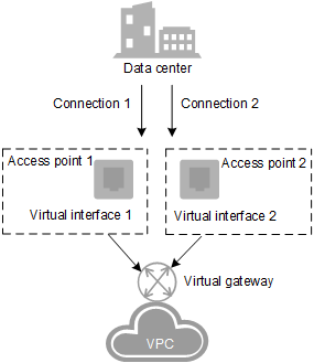
Figure 1 Redundant connection access
Operation Flowchart
You need to create two connections, with one connecting to Biere and the other to Magdeburg. Create a virtual gateway and access the VPC to which the services belong. Create two virtual interfaces and connect them to the same virtual gateway associated with the target VPC. Figure 2 shows how to create a redundant connection.
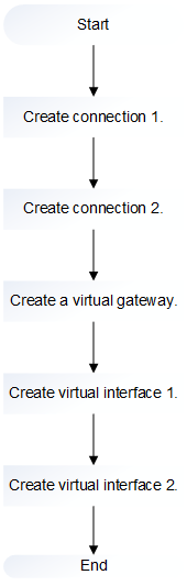
Figure 2 Flowchart for creating a redundant connection
Procedure
Creating a Connection
Log in to the management console.
Click
 in the upper left corner and select a region and a project.
Under Network, click Direct Connect.
In the navigation pane of Network Console, choose Direct Connect > Connections.
On the displayed Connections page, click Create Connection in the upper right corner to create the first connection.
Follow the prompts to set the following parameters.
Table 1 Connection parameters¶ Parameter
Description
Example Value
Region
Specifies the region in which the services will be handled.
If you already selected a region and a project on the management console, you do not need to select the region here.
eu-de
Name
Specifies the connection name.
It can contain 1 to 64 characters.
Only digits, letters, underscores (_), and hyphens (-) are allowed.
dc-123
Location
Specifies the connection access location.
You can select Biere or Magdeburg. The access location of the first connection must be different from that of the second connection.
Biere
Peering Position
Specifies the physical location of the connection. The address is an identifier.
Only letters, digits, underscores (_), and hyphens (-) are allowed.
It can contain 0 to 64 characters.
"Marderbug-DC01"
Bandwidth
Specifies the bandwidth size in the unit of Mbit/s.
You can select one of the bandwidths provided on the scroll bar by dragging it. Also, typing a value in the input field is allowed. It is automatically changed to the next allowed value shown on the slider bar.
100
Description
Provides supplementary information about the connection.
It can contain 0 to 128 characters.
This is a connection.
Click Create Now, confirm the connection details, and click Submit.
Note
Click Back to Connection List to view the created connections.
After clicking Submit, you will be automatically redirected to the connection list after a timeout.
Creating a Virtual Gateway
In the navigation pane on the left, choose Direct Connect > Virtual Gateways.
In the upper right corner of the Virtual Gateways page, click Create Virtual Gateway.
Follow the prompts to set the following parameters.
Table 2 Virtual gateway parameters¶ Parameter
Description
Example Value
Name
Specifies the virtual gateway name.
It can contain 1 to 64 characters.
Only digits, letters, underscores (_), and hyphens (-) are allowed.
vgw-123
VPC
Specifies the VPC that you need to access.
VPC-001
CIDR Block
Specifies the CIDR network segment of the VPC to be accessed by the direct connection.
You can add a maximum of 50 CIDR blocks. Each pair must be unique. Separate every two CIDR blocks with commas (,).
192.168.0.0/16
Description
Provides supplementary information about the virtual gateway.
It can contain 0 to 128 characters.
This is a virtual gateway.
Click OK.
Creating a Virtual Interface
In the navigation pane on the left, choose Direct Connect > Virtual Interfaces.
On the displayed Virtual Interfaces page, click Create Virtual Interface in the upper right corner to create the first virtual interface.
Follow the prompts to set the following parameters.
Table 3 Virtual interface parameters¶ Parameter
Description
Example Value
Region
Specifies the region in which the services will be handled.
If you already selected a region and a project on the management console, you do not need to select the region here.
eu-de
Name
Specifies the virtual interface name.
It can contain 1 to 64 characters.
Only digits, letters, underscores (_), and hyphens (-) are allowed.
vif-123
Connection
Specifies the connection to be associated.
Select the connection that is connected to Biere or Magdeburg. The access locations of the two connections must be different.
dc-123
Virtual Gateway
Select the virtual gateway to be associated.
vgw-123
VLAN
Specifies the virtual interface VLAN ID.
The system automatically allocates a VLAN ID. You do not need to set this parameter.
30
Bandwidth
Specifies the virtual interface bandwidth in the unit of Mbit/s.
If the selected connection is a hosting connection, the virtual interface exclusively uses the connection bandwidth. That is, the connection bandwidth is the bandwidth of the virtual interface.
100
Remote Subnet
Specifies the remote subnet and mask. You can enter a maximum of 50 remote subnets. Each pair must be unique. Separate every two remote subnets with commas (,).
The remote subnet of the virtual interface cannot be the same as the VPC CIDR block of the virtual gateway.
192.168.51.0/24
Description
Provides supplementary information about the virtual interface.
It can contain 0 to 128 characters.
This is a virtual interface.
Click Create Now.
Repeat step 1 to step 4 to create the second virtual interface.