Overview
You can learn about a cluster network from the following two aspects:
What is a cluster network like? A cluster consists of multiple nodes, and pods (or containers) are running on the nodes. Nodes and containers need to communicate with each other. For details about the cluster network types and their functions, see Cluster Network Structure.
How is pod access implemented in a cluster? Accessing a pod or container is a process of accessing services of a user. Kubernetes provides Service and Ingress to address pod access issues. This section summarizes common network access scenarios. You can select the proper scenario based on site requirements. For details about the network access scenarios, see Access Scenarios.
Cluster Network Structure
All nodes in the cluster are located in a VPC and use the VPC network. The container network is managed by dedicated network add-ons.
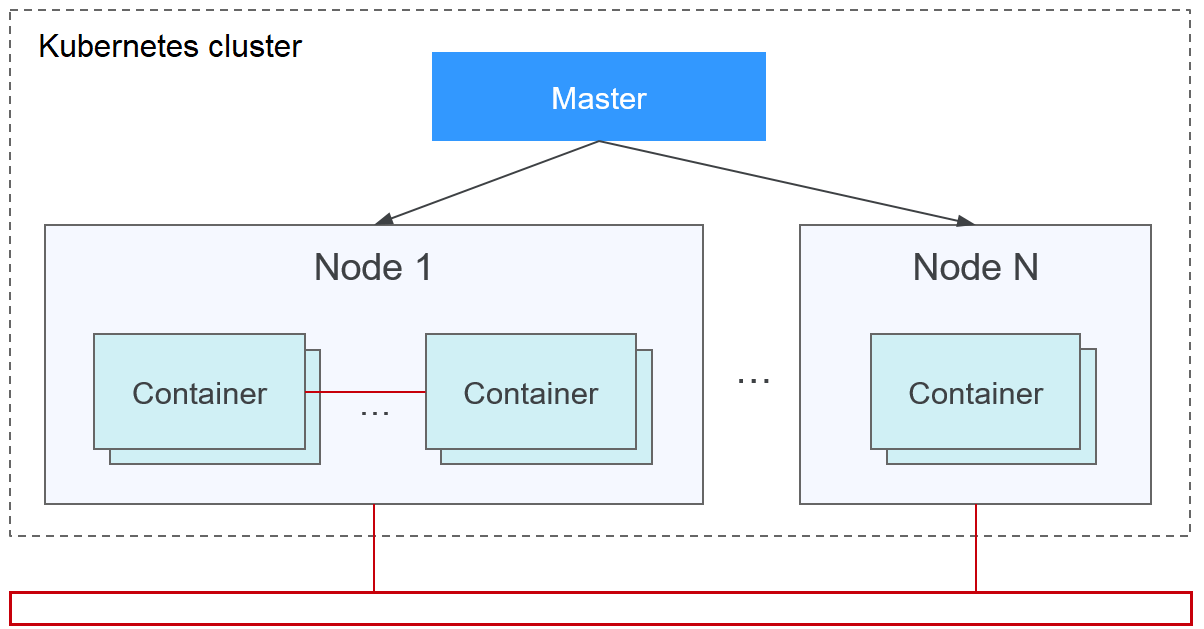
Node Network
A node network assigns IP addresses to hosts (nodes in the figure above) in a cluster. You need to select a VPC subnet as the node network of the CCE cluster. The number of available IP addresses in a subnet determines the maximum number of nodes (including master nodes and worker nodes) that can be created in a cluster. This quantity is also affected by the container network. For details, see the container network model.
Container Network
A container network assigns IP addresses to containers in a cluster. CCE inherits the IP-Per-Pod-Per-Network network model of Kubernetes. That is, each pod has an independent IP address on a network plane and all containers in a pod share the same network namespace. All pods in a cluster exist in a directly connected flat network. They can access each other through their IP addresses without using NAT. Kubernetes only provides a network mechanism for pods, but does not directly configure pod networks. The configuration of pod networks is implemented by specific container network add-ons. The container network add-ons are responsible for configuring networks for pods and managing container IP addresses.
Currently, CCE supports the following container network models:
Container tunnel network: The container tunnel network is constructed on but independent of the node network through tunnel encapsulation. This network model uses VXLAN to encapsulate Ethernet packets into UDP packets and transmits them in tunnels. Open vSwitch serves as the backend virtual switch.
VPC network: The VPC network uses VPC routing to integrate with the underlying network. This network model is applicable to performance-intensive scenarios. The maximum number of nodes allowed in a cluster depends on the route quota in a VPC network. Each node is assigned a CIDR block of a fixed size. This networking model is free from tunnel encapsulation overhead and outperforms the container tunnel network model. In addition, as VPC routing includes routes to node IP addresses and the container CIDR block, container pods in a cluster can be directly accessed from outside the cluster.
Developed by CCE, Cloud Native Network 2.0 deeply integrates Elastic Network Interfaces (ENIs) and Sub Network Interfaces (sub-ENIs) of VPC. Container IP addresses are allocated from the VPC CIDR block. ELB passthrough networking is supported to direct access requests to containers. Security groups and elastic IPs (EIPs) are bound to deliver high performance.
The performance, networking scale, and application scenarios of a container network vary according to the container network model. For details about the functions and features of different container network models, see Overview.
Service Network
Service is also a Kubernetes object. Each Service has a fixed IP address. When creating a cluster on CCE, you can specify the Service CIDR block. The Service CIDR block cannot overlap with the node or container CIDR block. The Service CIDR block can be used only within a cluster.
Service
A Service is used for pod access. With a fixed IP address, a Service forwards access traffic to pods and performs load balancing for these pods.
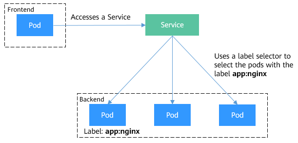
Figure 1 Accessing pods through a Service
You can configure the following types of Services:
ClusterIP: used to make the Service only reachable from within a cluster.
NodePort: used for access from outside a cluster. A NodePort Service is accessed through the port on the node.
LoadBalancer: used for access from outside a cluster. It is an extension of NodePort, to which a load balancer routes, and external systems only need to access the load balancer.
For details about the Service, see Service Overview.
Ingress
Services forward requests using layer-4 TCP and UDP protocols. Ingresses forward requests using layer-7 HTTP and HTTPS protocols. Domain names and paths can be used to achieve finer granularities.
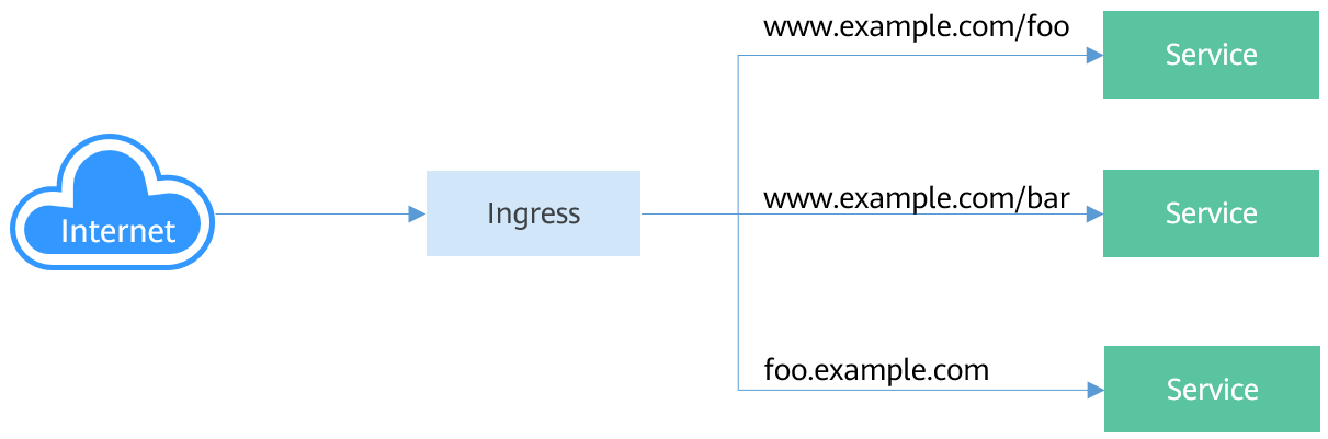
Figure 2 Ingress-Service
For details about the ingress, see Ingress Overview.
Access Scenarios
Workload access scenarios can be categorized as follows:
Intra-cluster access: A ClusterIP Service is used for workloads in the same cluster to access each other.
Access from outside a cluster: A Service (NodePort or LoadBalancer type) or an ingress is recommended for a workload outside a cluster to access workloads in the cluster.
Access through the internet requires an EIP to be bound the node or load balancer.
Access through the intranet requires an internal IP address to be bound the node or load balancer. If workloads are located in different VPCs, a peering connection is required to enable communication between different VPCs.
The workload accesses the external network.
Accessing an intranet: The workload accesses the intranet address, but the implementation method varies depending on container network models. Ensure that the peer security group allows the access requests from the container CIDR block.
Accessing a public network: You need to assign an EIP to the node where the workload runs (when the VPC network or tunnel network model is used), bind an EIP to the pod IP address (when the Cloud Native Network 2.0 model is used), or configure SNAT rules through the NAT gateway. For details, see Accessing Public Networks from a Container.
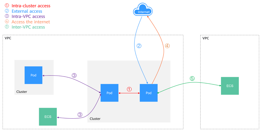
Figure 3 Network access diagram