Cloud Native 2.0 Network
Model Definition
Developed by CCE, Cloud Native 2.0 network deeply integrates Elastic Network Interfaces (ENIs) and sub-ENIs of Virtual Private Cloud (VPC). Container IP addresses are allocated from the VPC CIDR block. ELB passthrough networking is supported to direct access requests to containers. Security groups and EIPs are bound to deliver high performance.
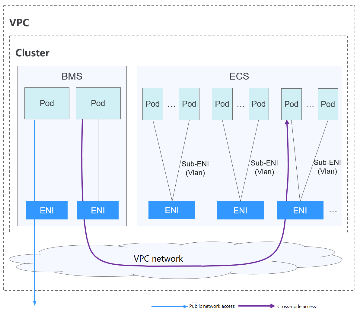
Figure 1 Cloud Native 2.0 network
Pod-to-pod communication
Pods on BMS nodes use ENIs, whereas pods on ECS nodes use Sub-ENIs. Sub-ENIs are attached to ENIs through VLAN sub-interfaces.
On the same node: Packets are forwarded through the VPC ENI or sub-ENI.
Across nodes: Packets are forwarded through the VPC ENI or sub-ENI.
Constraints
This network model is available only to CCE Turbo clusters.
Advantages and Disadvantages
Advantages
As the container network directly uses VPC, it is easy to locate network problems and provide the highest performance.
External networks in a VPC can be directly connected to container IP addresses.
The load balancing, security group, and EIP capabilities provided by VPC can be directly used by pods.
Disadvantages
The container network directly uses VPC, which occupies the VPC address space. Therefore, you must properly plan the container CIDR block before creating a cluster.
Application Scenarios
High performance requirements and use of other VPC network capabilities: Cloud Native Network 2.0 directly uses VPC, which delivers almost the same performance as the VPC network. Therefore, it applies to scenarios that have high requirements on bandwidth and latency.
Large-scale networking: Cloud Native Network 2.0 supports a maximum of 2000 ECS nodes and 100,000 containers.
Container IP Address Management
In the Cloud Native Network 2.0 model, ECS nodes use sub-ENIs.
The IP address of the pod is directly allocated from the VPC subnet configured for the container network. You do not need to allocate an independent small network segment to the node.
To add an ECS node to a cluster, bind the ENI that carries the sub-ENI first. After the ENI is bound, you can bind the sub-ENI.
Number of ENIs bound to an ECS node: For clusters of v1.19.16-r40, v1.21.11-r0, v1.23.9-r0, v1.25.4-r0, v1.27.1-r0, and later versions, the value is 1. For clusters of earlier versions, the value is the maximum number of sub-ENIs that can be bound to the node divided by 64 (rounded up).
ENIs bound to an ECS node = Number of ENIs used to bear sub-ENIs + Number of sub-ENIs currently used by pods + Number of pre-bound sub-ENIs
When a pod is created, an available ENI is randomly allocated from the prebinding ENI pool of the node.
When the pod is deleted, the ENI is released back to the ENI pool of the node.
When a node is deleted, the ENIs are released back to the pool, and the sub-ENIs are deleted.
Cloud Native Network 2.0 supports dynamic ENI pre-binding policies. The following table lists the scenarios.
Policy | Dynamic ENI Pre-binding Policy (Default) |
|---|---|
Management policy | nic-minimum-target: minimum number of ENIs (pre-bound and unused + used) bound to a node. nic-maximum-target: If the number of ENIs bound to a node exceeds the value of this parameter, the system does not proactively pre-bind ENIs. nic-warm-target: minimum number of pre-bound ENIs on a node. nic-max-above-warm-target: ENIs are unbound and reclaimed only when the number of idle ENIs minus the number of nic-warm-target is greater than the threshold. |
Application scenario | Accelerates pod startup while improving IP resource utilization. This mode applies to scenarios where the number of IP addresses in the container network segment is insufficient. |
CCE provides four parameters for the dynamic ENI pre-binding policy. Set these parameters properly.
Parameter | Default Value | Description | Suggestion |
|---|---|---|---|
nic-minimum-target | 10 | Minimum number of ENIs bound to a node. The value can be a number or a percentage.
Set both nic-minimum-target and nic-maximum-target to the same value or percentage. | Set these parameters based on the number of pods. |
nic-maximum-target | 0 | If the number of ENIs bound to a node exceeds the value of nic-maximum-target, the system does not proactively pre-bind ENIs. If the value of this parameter is greater than or equal to the value of nic-minimum-target, the check on the maximum number of the pre-bound ENIs is enabled. Otherwise, the check is disabled. The value can be a number or a percentage.
Set both nic-minimum-target and nic-maximum-target to the same value or percentage. | Set these parameters based on the number of pods. |
nic-warm-target | 2 | Minimum number of pre-bound ENIs on a node. The value must be a number. When the value of nic-warm-target + the number of bound ENIs is greater than the value of nic-maximum-target, the system will pre-bind ENIs based on the difference between the value of nic-maximum-target and the number of bound ENIs. | Set this parameter to the number of pods that can be scaled out instantaneously within 10 seconds. |
nic-max-above-warm-target | 2 | Only when the number of idle ENIs on a node minus the value of nic-warm-target is greater than the threshold, the pre-bound ENIs will be unbound and reclaimed. The value can only be a number.
| Set this parameter based on the difference between the number of pods that are frequently scaled on most nodes within minutes and the number of pods that are instantly scaled out on most nodes within 10 seconds. |
Note
The preceding parameters support global configuration at the cluster level and custom settings at the node pool level. The latter takes priority over the former.
The container networking component maintains a scalable pre-bound ENI pool for each node. The component checks and calculates the number of pre-bound ENIs or idle ENIs every 10 seconds.
Number of pre-bound ENIs = min(nic-maximum-target - Number of bound ENIs, max(nic-minimum-target - Number of bound ENIs, nic-warm-target - Number of idle ENIs)
Number of ENIs to be unbound = min(Number of idle ENIs - nic-warm-target - nic-max-above-warm-target, Number of bound ENIs - nic-minimum-target)
The number of pre-binding ENIs on the node remains in the following range:
Minimum number of ENIs to be pre-bound = min(max(nic-minimum-target - Number of bound ENIs, nic-warm-target), nic-maximum-target - Number of bound ENIs)
Maximum number of ENIs to be pre-bound = max(nic-warm-target + nic-max-above-warm-target, Number of bound ENIs - nic-minimum-target)
When a pod is created, an idle ENI (the earliest unused one) is preferentially allocated from the pool. If no idle ENI is available, a newsub-ENI is bound to the pod.
When the pod is deleted, the corresponding ENI is released back to the pre-bound ENI pool of the node, enters a 2 minutes cooldown period, and can be bind to another pod. If the ENI is not bound to any pod within 2 minutes, it will be released.
Recommendation for CIDR Block Planning
As described in Cluster Network Structure, network addresses in a cluster can be divided into three parts: node network, container network, and service network. When planning network addresses, consider the following aspects:
The three CIDR blocks cannot overlap. Otherwise, a conflict occurs. All subnets (including those created from the secondary CIDR block) in the VPC where the cluster resides cannot conflict with the container and Service CIDR blocks.
Ensure that each CIDR block has sufficient IP addresses.
The IP addresses in the node CIDR block must match the cluster scale. Otherwise, nodes cannot be created due to insufficient IP addresses.
The IP addresses in the container CIDR block must match the service scale. Otherwise, pods cannot be created due to insufficient IP addresses.
In the Cloud Native Network 2.0 model, the container CIDR block and node CIDR block share the network addresses in a VPC. It is recommended that the container subnet and node subnet not use the same subnet. Otherwise, containers or nodes may fail to be created due to insufficient IP resources.
In addition, a subnet can be added to the container CIDR block after a cluster is created to increase the number of available IP addresses. In this case, ensure that the added subnet does not conflict with other subnets in the container CIDR block.
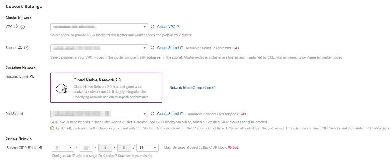
Figure 2 Configuring CIDR blocks
Example of Cloud Native Network 2.0 Access
Create a CCE Turbo cluster, which contains three ECS nodes.
Access the details page of one node. You can see that the node has one primary ENI and one extended ENI, and both of them are ENIs. The extended ENI belongs to the container CIDR block and is used to mount a sub-ENI to the pod.
Create a Deployment in the cluster.
kind: Deployment
apiVersion: apps/v1
metadata:
  name: example
  namespace: default
spec:
  replicas: 6
  selector:
    matchLabels:
      app: example
  template:
    metadata:
      labels:
        app: example
    spec:
      containers:
        - name: container-0
          image: 'nginx:perl'
          resources:
            limits:
              cpu: 250m
              memory: 512Mi
            requests:
              cpu: 250m
              memory: 512Mi
      imagePullSecrets:
        - name: default-secret
View the created pod.
$ kubectl get pod -owide
NAME                       READY   STATUS    RESTARTS   AGE   IP            NODE         NOMINATED NODE   READINESS GATES
example-5bdc5699b7-54v7g   1/1     Running   0          7s    10.1.18.2     10.1.0.167   <none>           <none>
example-5bdc5699b7-6dzx5   1/1     Running   0          7s    10.1.18.216   10.1.0.186   <none>           <none>
example-5bdc5699b7-gq7xs   1/1     Running   0          7s    10.1.16.63    10.1.0.144   <none>           <none>
example-5bdc5699b7-h9rvb   1/1     Running   0          7s    10.1.16.125   10.1.0.167   <none>           <none>
example-5bdc5699b7-s9fts   1/1     Running   0          7s    10.1.16.89    10.1.0.144   <none>           <none>
example-5bdc5699b7-swq6q   1/1     Running   0          7s    10.1.17.111   10.1.0.167   <none>           <none>
The IP addresses of all pods are sub-ENIs, which are mounted to the ENI (extended ENI) of the node.
For example, the extended ENI of node 10.1.0.167 is 10.1.17.172. On the Network Interfaces page of the Network Console, you can see that three sub-ENIs are mounted to the extended ENI 10.1.17.172, which is the IP address of the pod.
In the VPC, the IP address of the pod can be successfully accessed.