Configuring a User-defined VLAN (Windows Server)
This section uses Windows Server 2012 R2 Standard as an example to describe how to configure a user-defined VLAN for BMSs.
Note
The configuration methods of other Windows Server OSs are similar to that of Windows Server 2012 R2 Standard.
Log in to a Windows BMS.
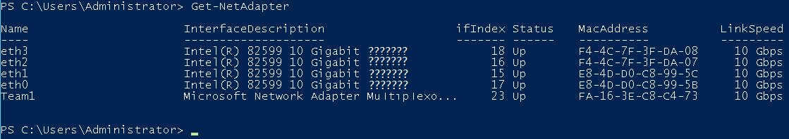
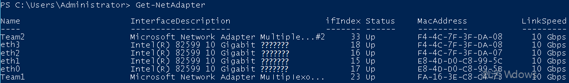
On the Windows PowerShell CLI of the BMS, run the following command to check the NIC information:
Get-NetAdapter
Information similar to the following is displayed.
Note
Among the devices, eth0 and eth1 bear the VPC, and eth2 and eth3 bear the user-defined VLAN. The following steps use eth2 and eth3 to configure a user-defined VLAN.
To improve the outbound traffic on the OS, perform the operations in Method 1. If there is no special requirement on traffic, perform the operations in Method 2.
Method 1: Use the switch independent mode for the team in the OS. The outbound traffic is distributed across all active NICs, and the inbound traffic is received through one of the NICs in the team.
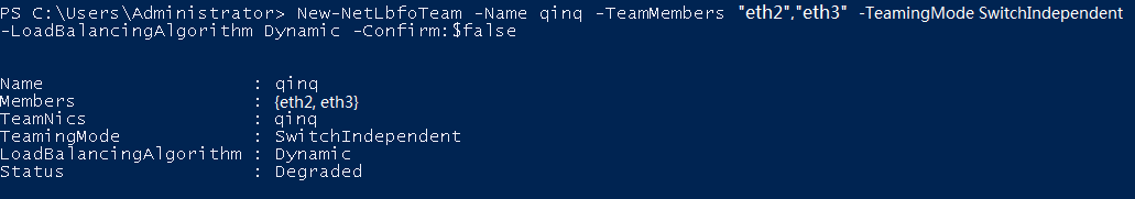
Run the following command to create a port group for the user-defined VLAN:
New-NetLbfoTeam -Name qinq -TeamMembers "eth2","eth3" -TeamingMode SwitchIndependent -LoadBalancingAlgorithm Dynamic -Confirm:$false
Note
In the command, qinq is the name of the port group planned for the user-defined VLAN, and eth2 and eth3 are the network devices that bear the user-defined VLAN obtained in step 2.
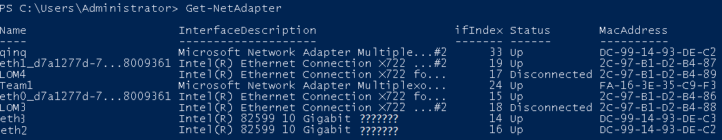
Run the following command to query the network adapters:
Get-NetLbfoTeamMember
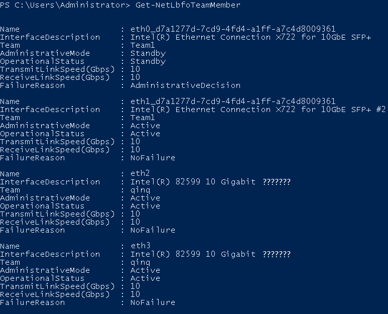
Get-NetAdapter
Method 2: Use the active-active mode for the team in the OS.
Run the following command to create a port group for the user-defined VLAN:
New-NetLbfoTeam -Name Team2 -TeamMembers "eth2","eth3" -TeamingMode SwitchIndependent -LoadBalancingAlgorithm IPAddresses -Confirm:$false
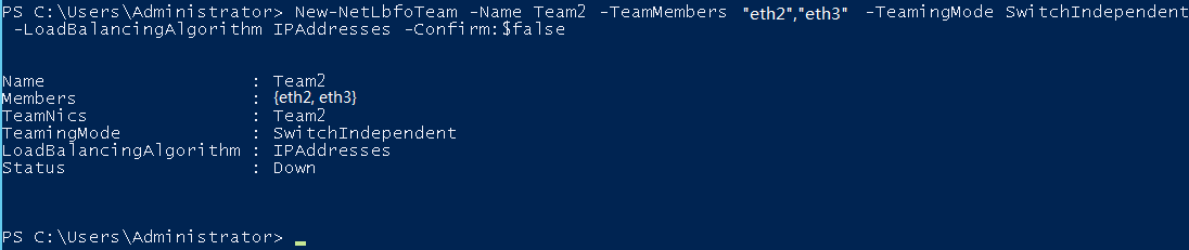
Note
In the command, Team2 is the name of the port group planned for the user-defined VLAN, and eth2 and eth3 are the network devices that bear the user-defined VLAN obtained in step 2.
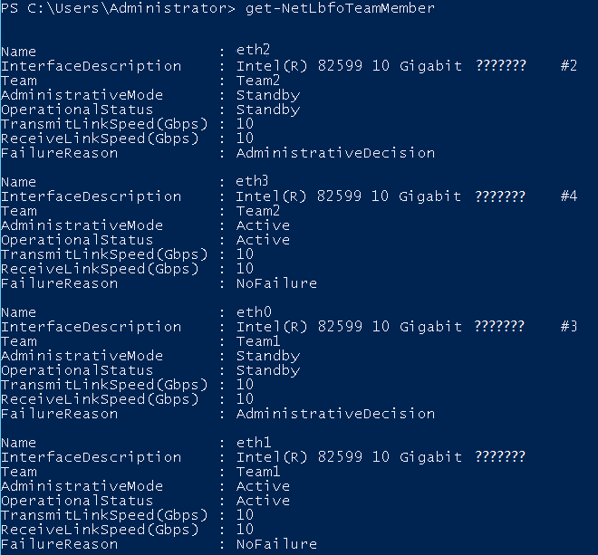
Run the following command to set a network port of port group Team2 created in 3.a to the standby port:
Set-NetLbfoTeamMember -Name "eth2" -AdministrativeMode Standby -Confirm:$false
Note
The port group configured for the user-defined VLAN supports only the active/standby mode. eth2 is one of the ports of the port group. You can determine which port is configured as the standby port based on your planning.
get-NetLbfoTeamMember
Get-NetAdapter
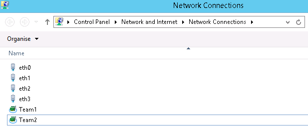
Run the following command to enter the Network Connections page:
ncpa.cpl
Then enter the following page.
Configure a user-defined VLAN.
On the Network Connections page, double-click port group Team2 created in 3 to switch to the Team2 Status page.
Click Next to switch to the Team2 Properties page.
On the Networking tab page, double-click Internet Protocol Version 4 (TCP/IPv4) to switch to the Internet Protocol Version 4 (TCP/IPv4) Properties page.
Select Use the following IP address, configure the IP address and subnet mask, and click OK.
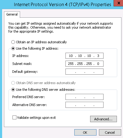
Note
If the IP address planned for the user-defined VLAN does not conflict with the VPC network segment, you can plan the IP address as needed, only to ensure that BMSs communicating through the user-defined VLAN are in the same network segment as the user-defined VLAN.
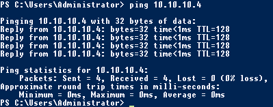
Perform the preceding operations to configure other BMSs.
After all BMSs are configured, ping the IP addresses of other BMSs from each BMS.
If you want to configure VLAN sub-interfaces to isolate network planes, perform the following operations:
Run the following command to create a VLAN sub-interface based on the existing Team2:
Add-NetLbfoTeamNIC -Team "Team2" -VlanID XXX -Confirm:$false
In the preceding command, Team2 indicates the bond name, and XXX indicates the VLAN ID.
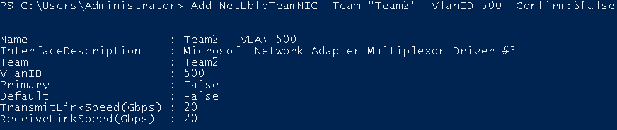
After the VLAN sub-interface is created, configure the IP address and subnet mask of network port Team2-VLAN 500 by referring to 4 and 5.